From Astounding Science Fiction of May, 1949, the article “Electrical Mathematicians,” by Lorne Maclaughlan, focuses on the the use of computers – specifically, electronic as opposed to mechanical computers – as devices to perform mathematical calculations. It’s one of the four non-fiction articles pertaining to cybernetics and computation published by the magazine that year, the other three having been:
“Modern Calculators” (digital and analog calculation), by E.L. Locke; pp. 87-106 – January
“The Little Blue Cells” (‘Selectron’ data storage tube), by J.J. Coupling; pp. 85-99 – February
“Cybernetics” (review of Norbert Wiener’s book by the same title), by E.L. Locke; pp. 78-87 – September
The identity and background of author Maclaughlan remain an enigma. (At least, in terms of “this” post!) The Internet Speculative Fiction Database lists only two other entries under his name, both in Astounding (“Noise from Outside” in 1947, and “Servomechanisms” in 1948, while web searches yield a parallel paucity of results. This absence biographical information, especially in light of the over seven decades that have transpired since 1949, coupled with the author’s distinctive writing style – combining clarity and economy of expression, and easy familiarity with the language of technology – leads me to wonder if that very name “Lorne Maclaughlin” (note the lack of a middle initial?) might actually have been a pen-name for an engineer or academic. Given the somewhat ambiguous reputation of science-fiction in professional and credentialed circles (albeit a reputation by the 1940s changing for the better) maybe “Maclaughlan” – assuming the name was a pseudonym – might have wanted to maintain a degree of anonymity.
Well, if so (maybe so?!) that anonymity has successfully persisted to this day!
Anyway, the cover art’s cool.
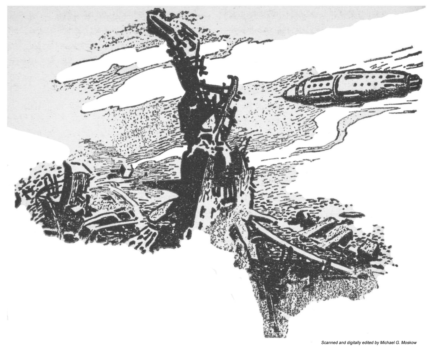
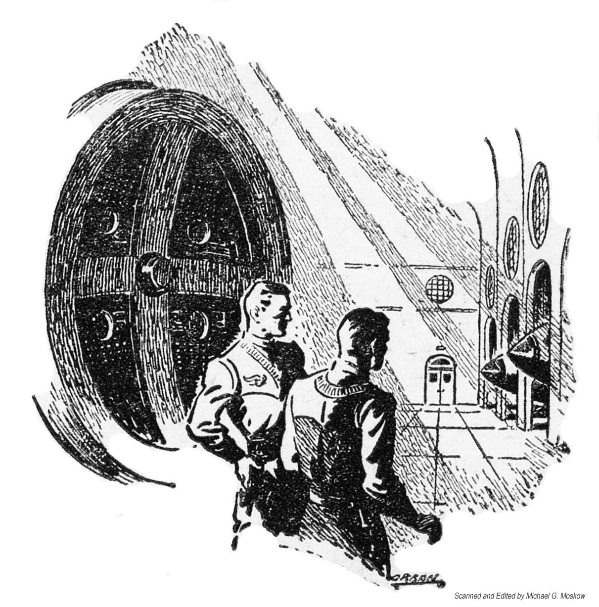
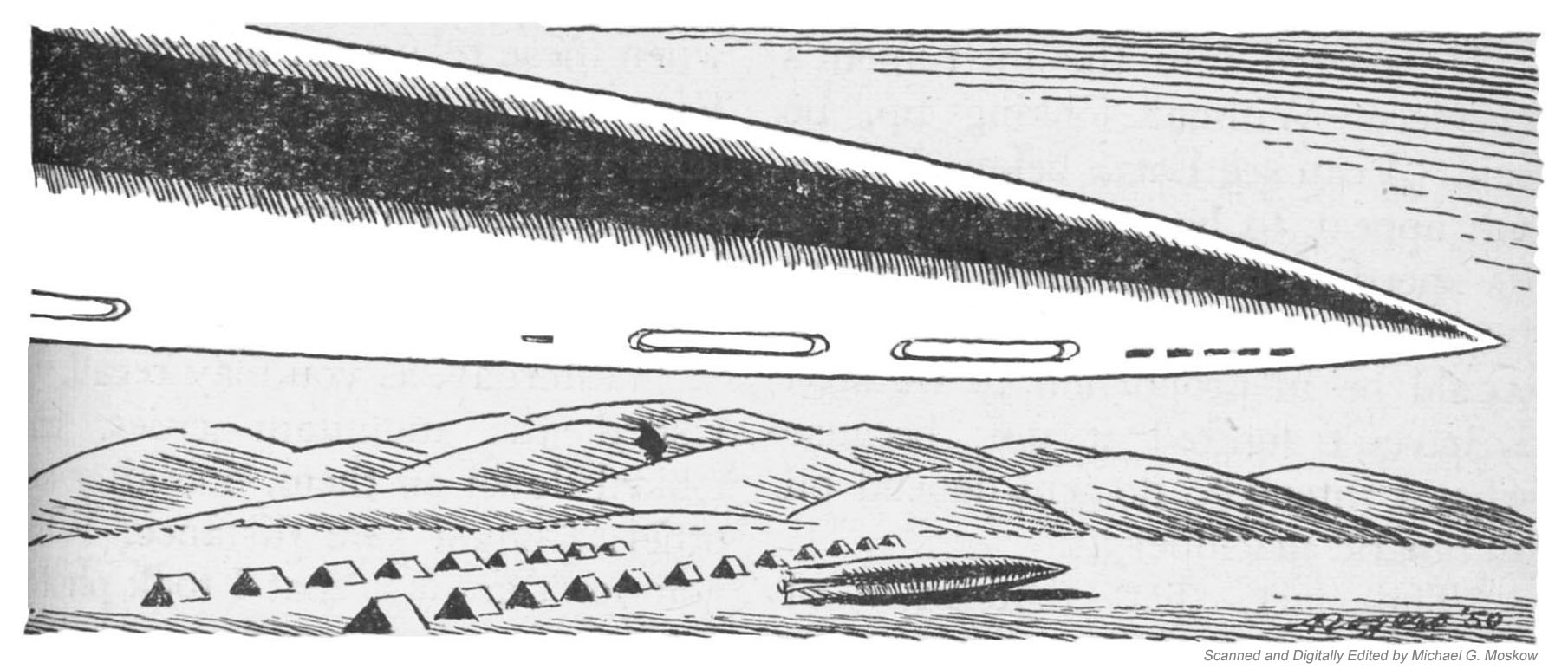
Depicting a scene from the opening of Hal Clement’s serialized novel Needle (the inspiration for the 1987 Kyle MacLachlan film The Hidden?), it’s one of the three (color, naturally) Astounding Science Fiction cover illustrations by Paul Orban, an illustrator primarily known for his fabulously imaginative interior work, whose abundant output was only exceeded by his talent.

As for Maclaughlan’s article itself, it begins with a brief overview of the implications of the increasing centrality of calculating devices in contemporary (1949 contemporary, that is!) society, and the future.
This is followed by a discussion of the very nature of calculation, whether performed by mechanical or electronic devices, which then segues into a comparison of the similarities and differences between binary and decimal systems of counting and computation, and an explanation of the utility of the former in computing devices.
Next, a lengthy discussion of memory. (We’ve all heard of that…) note the statement, “Not only must we “teach” the machine the multiplication table – by the process of wiring in the right connections – but it may also be necessary to provide built-in tables of sine and cosine functions, as well as other commonly used functions. This is a permanent kind of memory – a fast temporary kind of memory is also needed to remember such things as the product referred to above until it is no longer needed. This memory has not been easy to provide in required amounts, but recently invented electronic devices seem to offer some hope that this difficulty can be overcome.” In this, author Maclaughlan is anticipating what we know today as ROM (read-only-memory) and RAM (random-access-memory), respectively.
This is followed by the topic of data input and manipulation, in the context of Hollerith Cards and Charles Babbage’s “Difference Engine”. (For the latter, see “Babbage’s First Difference Engine – How it was intended to work,” and, “The Babbage Engine,” the latter at Computer History Museum.
From this, we come to computation in terms of the technology and operation of then-existing computers. This encompasses ENIAC (Electronic Numerical Integrator and Computer), EDVAC (Electronic Discrete Variable Automatic Computer), and MANIAC (Mathematical Analyzer Numerical Integrator and Automatic Computer Model I), and briefly touches upon the Selectron tube, the latter device the subject of J.J. Coupling’s article in the February 1949 issue of Astounding.
The final part of Mclaughlan’s article is a discussion of the nature, advantages, and use of “analyzers” – Differential Analyzers, and Transient Network Analyzers – in computation: Specifically, in the solution of differential equations pertinent to scientific research, such as, “…the flow of microwave energy in wave-guides, the flow of compressible fluids in pipes, and even the solution of Schrodinger’s Wave Equation,” or military applications, such as aiming anti-aircraft guns or determining the trajectory of nuclear weapons, noting, “These latter-day buzz-bombs will be sufficiently lethal to warrant their carrying along their own computers.”
Prescience, or, inevitability?
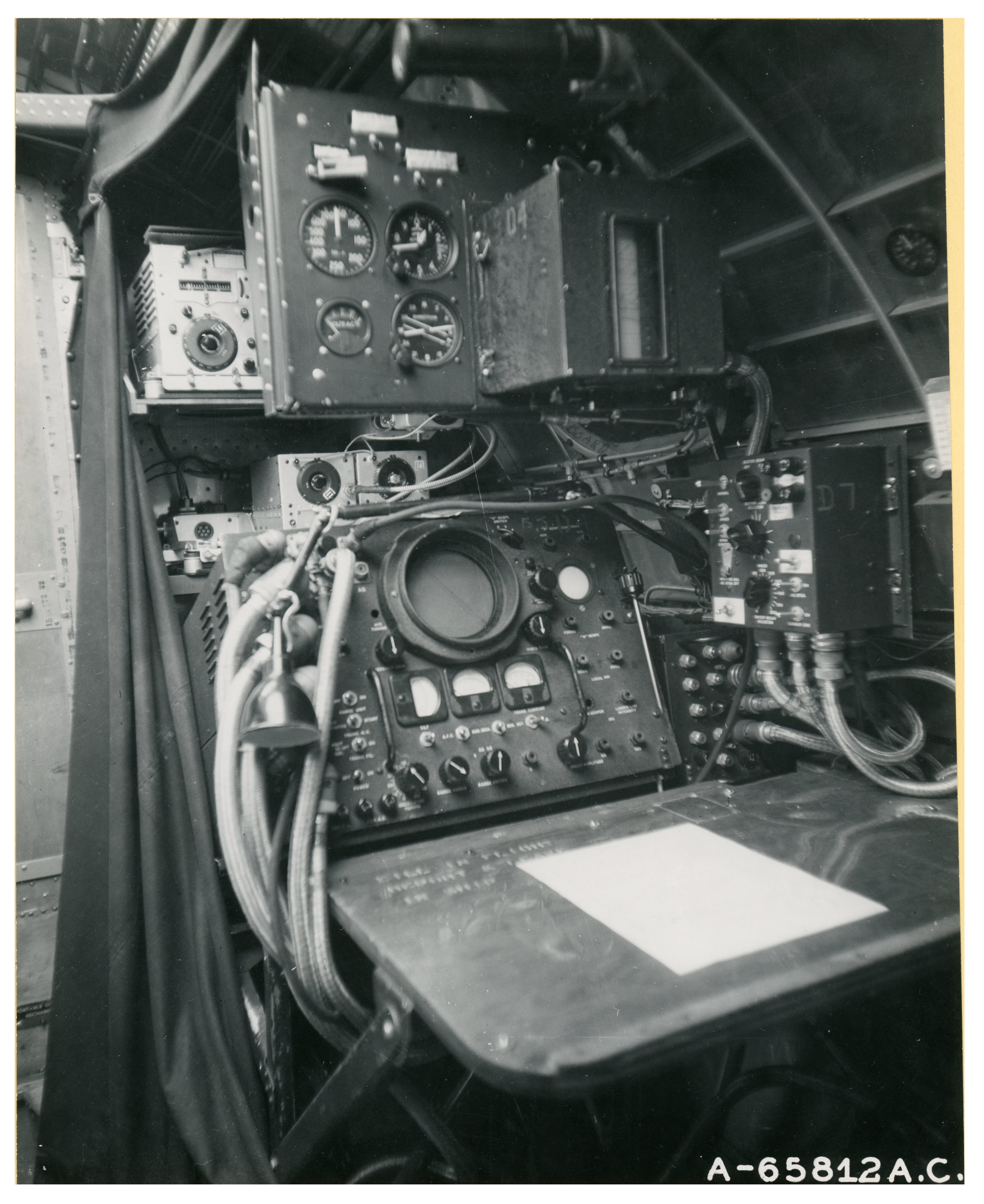
And finally, the article concludes with a photograph.
And, so…
ELECTRICAL MATHEMATICIANS
“The differential analyzer is more versatile than the network analyzer discussed above because it can integrate, differentiate – in effect – and multiply, and thus solve rather complicated differential equations. These functions are performed by mechanical or electro-mechanical devices in the differential analyzer. If these things could be accomplished by purely electrical means, we would expect a great increase in speed, and some decrease in size and weight.”
To an extent none of us today can realize, these rapidly growing electrical calculators will become more and more important factors in ordinary life. So far, they are handling only simple, straight-arithmetic problems. They are brains, but so far they think only on low levels. Give them time; they will be planners yet!
In this machine age no one is surprised at the announcement of some new or improved labor-saving device. The scientists and technologists who design our new electronic rattraps, microwave hot-dog dispensers and atomic power plants have succeeded so well that they have created a serious manpower shortage in their own professions. This shortage, which is chiefly in the field of analysis has recently forced them to put an unprecedented amount of effort into the design of machines to save themselves mental labor. The results of their efforts are an amazingly variegated collection of computing machines, or “artificial brains” as they are called in the popular press:
The development of such machines took a tremendous spurt during the war, and today we can scarcely find a laboratory or university in the land which is not devoting some part of its efforts to work of this kind. Progress is so rapid that the machines are obsolete before they are completed, and thus no two identical machines exist.
We cannot say that the computing machine is a new invention – the unknown Chinese originator of the abacus provided man with his first calculating machine in the sixth century B.C. This would seem to make the machine nearly as old as the art of calculating, but man is equipped with fingers and toes which have always provided a handy portable computing device. In fact, as we shall see, the simple fact that we have ten lingers has a definite bearing on the number of tubes and the kind of circuits required in electronic digital computers.
__________
Kelvin Wheel-and-Disk integrator. This device, which gives the integral of a radial distance with respect to an angle, is the most important unit in a differential analyzer of the electromechanical type.

__________
It should be pointed out that there are two distinct types of computing machines in common use today. One type deals with discrete whole numbers, counting them off with the aid of teeth on a wheel, or electrical pulses in vacuum tube circuits. These numbers represent quantities, and they are added and multiplied just as numbers are on paper, but at a much higher speed. These machines called digital computers, range from the simple cash-register adding machine to the complex all-electric ENIAC, with its eighteen thousand radio-type vacuum tubes.
The other type of machine is the analogue type of computer, in which the number to be dealt with is converted into some measurable quantity, such as length along a slide rule, or angle of rotation of a shaft. The operations are performed electrically or mechanically, and the answer appears as a length, an angle, a voltage or some other quantity which must be converted back to a number. The ideal machine of the analogue type will accept mathematical functions, empirical curves and directions for mixing and stirring, and turn out results in the form of curves automatically.
The digital computer is much more accurate than the analogue type for the simple reason that is easy to extend the number of significant digits in such machines to something like thirty or forty. It is impossible to measure a point on a curve to anything approaching one part in 1040. However, the analogue computers are in many ways faster and more versatile, because they can perform certain difficult mathematical operations directly, while digital machines require that these operations be reduced to addition and multiplication.
One of the first things we must do to understand modern digital computing machines is to disconnect our minds from the decimal number system, and get a more basic concept of number representation. The decimal system of numbers is a natural choice, based on the fact man has that ten fingers. We would perhaps be more fortunate had evolution given us twelve, for then our number system would be the more convenient duo-decimal system. Let us examine this system as a starting point, by studying the table of numbers below.
| 1 | 2 | 3 | 4 | 5 | 6 | 7 | 8 | 9 | * | t | 10 |
| 11 | 12 | 13 | 14 | 15 | 16 | 17 | 18 | 19 | 1* | t | 20 |
| 21 | 22 | 23 | 24 | 25 | 26 | 27 | 28 | 29 | 2* | t | 30 |
The six-fingered man would count to six on one hand, and then continue, seven, eight, nine, star, dagger, ten on the other. His ten would be our twelve, of course, but it would be a resting point for him while he got his shoes off to continue to his twenty – our twenty-four – on his twelve toes.
If we continue the table for twelve lines of twelve numbers each we will get to his one hundred, which corresponds to our one hundred forty-four. This number is his ten squared – our twelve squared – as it would be, and is preceded by his daggerty-dagger, ††. This duodecimal system has the advantage that ten can be divided by 2, 3, 4 and 6, giving in each case whole numbers – 10/4 = 3, 10/6 = 2, et cetera – while our ten is only divisible by 2 and 5. The ancient Babylonians were fond of this system, and also used sixty as a number base. These systems remain today as the bases of our measurement of time in seconds, minutes and hours.
Now let us examine the binary system, based on two. In this system all numbers are made up of combinations of just two digits, one and zero. The simplicity of this system makes it possible to use simple devices such as electromagnetic relays to represent numbers. The simple relay has two possible positions, open and closed, and we can represent zero by means of the open position, and one by the closed position, and then build up any number as shown in the table below.
| Decimal System | Binary System |
| 1 | 1 |
| 2 | 10 |
| 3 | 11 |
| 4 | 100 |
| 5 | 101 |
| 6 | 110 |
| 7 | 111 |
| 8 | 1000 |
| 9 | 1001 |
| 10 | 1010 |
Computation is easy with this system, once we get the hang of it. Thus our two cubed becomes, 1011 = 10 x 10 x 10 = 1000, and our two times three becomes 10 x 11 = 110, which is our six, as it should be.
With our minds cleared for action on any number base let us consider the capabilities which are necessary in a digital computer. Digital computation requires that all operations be reduced to those of addition, subtraction, multiplication and division whether a machine is used or not. These operations involve certain reflex actions, such as the response “six” when presented with the numbers “two” and “three” and the idea “multiply.” The trained human mind possesses such reflex actions, and the machine must also possess them, as a first requirement. Simple computing devices such as the commercial accounting machine possess a few reflexes. It is necessary to build many rapid reflexes into mathematical computing machines.
The next “mental” capability the machine must possess is that of memory. When we must multiply two numbers together before adding them to a third, memory is needed to preserve the product until the second operation can be performed. Commercial calculating machines have limited memory – after multiplication, for example, the number appears on the output wheels, and the third number can easily be added. The memory requirements in a good mathematical machine are much, much more stringent, and provide some of the toughest problems in design. Not only must we “teach” the machine the multiplication table – by the process of wiring in the right connections – but it may also be necessary to provide built-in tables of sine and cosine functions, as well as other commonly used functions. This is a permanent kind of memory – a fast temporary kind of memory is also needed to remember such things as the product referred to above until it is no longer needed. This memory has not been easy to provide in required amounts, but recently invented electronic devices seem to offer some hope that this difficulty can be overcome.
There are still two capabilities left. These are choice and sequence. The computing machine should be able to choose between two numbers, or two operations it can perform, in accordance with certain rules. Sequence involves, as the name implies, the proper choice of order of numbers or operations according to some rule which applies in the particular problem being solved.
These last two capabilities are not found to any great extent in any but the most modern mathematical computing machines. On the other hand there are a multitude of other mental capabilities found in humans which are undesirable in mathematical machines. Emotion, aesthetics, creative ability and so forth are not desirable, for these help to make humans unfit for much routine computing work. What we want is perfect slave, fast, untiring and industrious, who will never embarrass or disconcert us with unexpected response. (Of course the engineers in charge of some of the complicated modern mathematical machines are quick to accuse them of temper tantrums and other undesirable emotions.)
Perhaps the fanciest digital computing machine today is the IBM Automatic Sequence Controlled calculator at Harvard. The letters IBM International Business Machines Corporation, which has developed a series of machines intended for use in accounting work. These machines use a punched card – a device with quite a history, as histories go in the computing field. It would seem that weaving machines which could be used to more or less automatically weave patterned cloth excited the imagination of a good many inventors in in the early eighteenth century. In such weaving it was necessary to sequence automatically the “shredding,” or controlling of the warp threads so that weft threads could be passed through them to weave a pattern. Punched tape and punched cards had already been by 1727. The punched cards we use today get the name Jacquard cards from the name of the inventor of an improved weaving machine around the year 1800.
This basic idea was good enough to attract the attention of Charles Babbage, an English actuary, who is regarded as the lather of the modern computing machine. His “difference engine” was designed, in his words, “to perform the whole operation” – of the computing and printing of tables of functions – “with no mental attention when numbers have once been fed in the machine.” When this “engine” was nearly complete the government withdrew its support of the Project, and Babbage began the construction of an analytical machine on his own. This machine, a wholly mechanical device, was to use punched Jacquard cards for automatic sequencing. In 1906 his son successfully completed a machine with which he calculated pi to twenty-nine significant figures.
Hollerith, in this country, made a great advance in the use of punched cards when he invented a card sorter to aid in classifying the results of the 1880 census. Most people today are familiar with the kind of things that a sorter can do. Thus if we have a sorter and a stack of cards with personal and alphabetical information punched thereon we can request the machine to pick out all left-handed individuals with cross-eyes and Z for a second initial, and bzzzzt, bzzzzt, bzzzzt – there they are.
The IBM Company, by catering to the needs of organizations which handle – and have – a good deal of money, was able to put the manufacture of computing machines on a paying basis. It need not be pointed out that it is much more difficult to produce profitably machines which will only be used for such tasks as the calculation of pi to umpteen places. However the punched card machines built for accountants have found their way into scientific computing laboratories, and the IBM Company has a research laboratory which is actively developing new machines for scientific use as well as for accounting.
A punched card machine operating on the Hollerith principle interprets numerical and operational data according to the positions of holes punched on cards, and then perform various mathematical operations. The cards, which are familiar to most people – postal notes, government checks, et cetera – have twelve vertical positions in each of eighty columns. The vertical positions are labeled y, x, 0, 1, 2, 3, 4, 5, 6, 7, 8, 9. Thus an 80 digit or two 40 digit numbers can be set up on one card, and the y space, for example, may be used to indicate sign.
The cards are read for purposes of sorting et cetera by a simple mechanism involving a metal cylinder and sets of electrically conducting brushes. As the card moves between the rotating cylinder and the eighty brushes, one for each column, an electrical contact is made whenever a punched hole passes under a brush. The position of the cylinder at the time that the brush makes contact indicates the number, or letter, represented. Any number system could be used, but the decimal system is selected because of its familiarity. The various IBM machines now on the market include Card Punchers, Card Interpretaters [sic], Card Sorters, Collators and others, all operating on the same basic principles. The most useful machine to scientific workers is the Automatic Multiplying Punch. This machine will multiply factors punched in cards, and will automatically punch the product in a card, or even add and punch out products.
The computer lab at Harvard, mentioned above, uses a combination of these machines and a device for sequencing their operations – whence the name IBM Automatic Sequence Controlled. This calculator is one of the half-dozen large machines in this country which can be used to tear into a tough problem and quickly reduce it to a neat column of figures – or a stack of cards, in this case. Since it is a digital type of computer capable of great accuracy, but because it is partly mechanical in operation it is slow compared to the newer all electronic machines. The automatic sequencing apparatus is not easy to set up, and thus type of machine is best suited to the solution of repetitive types of problems, such as the calculation of tables. The punched card is a convenient form in which to store tables of simple functions, e.g. Sin x, Log x, which are often needed in computation of tables of more complicated functions.
Of course, if you want to prepare a table umpteen places Bessell Functions, or evaluate some determinants, or make some matrix algebra manipulations you will have to wait s time for your turn on this or any similar machine. You will have to have a pretty good story too, for these machines are at work today, and sometimes night as well with important problems. It must be realized too, that a problem be rather important and complex before it is even worthwhile to the labor of setting it up for solution in such a complicated machine.
Punched cards are often used to store scientific data other than tables with the advantages of machine sorting et cetera possible with IBM machines. Thus at the Caltech wind tunnel data from instruments is punched directly on cards. Astronomers locate star images by pre-computed co-ordinates on punched cards, and then measure the star positions accurately and record the new information on new cards. The Census Bureau makes a great deal of use of punched cards at present, but plans are being made to go over to the faster electronic computers for this work.
__________
Basic flip-flop vacuum-tube circuit used in the ENIAC and in other digital computers. Tube number 2 – shaded – is conducting, and tube number 1 is “cut-off”, in the diagram above. A positive pulse on tube 1 will cause it to conduct and the resultant drop in its plate voltage will cause tube 2 to cease conducting. This condition is stable until another pulse arrives, on the grid of tube 2.

__________
Shortly before the war, G.R. Stibitz and others at the Bell Telephone Laboratories developed a relay type of computer which could handle not only real numbers but complex numbers as well. The binary number system is convenient in a relay computer as we have pointed out. There is some difficulty entailed in the process of getting from a number expressed in the ordinary decimal system to the binary system and back again. For this reason Stibitz likes what he calls a bi-quinary system, which uses base 2 to tell if a number is between 0 and 4, or 5 and 9, and base 5 to tell which digit it is of the five. Early in the war the Army and Navy each ordered one of these relay computers, and machine computation was off to a flying start.
Dr. H.H. Aiken, who had built the IBM computer at Harvard has recently gone over to the relay type of computer, and his “Mark II” will soon be in operation on the complicated guided missile ballistics problems being studied at the Dahlgren Proving Ground. IBM has also been playing around with relay computers, and has delivered two sequence controlled machines of this type for ballistic research workers. Aiken does his sequencing with standard teletype tape, while some of the IBM jobs use plugboards.
An interesting example of a similar parallel development is the Zuse computer, named after its designer Conrad Zuse, who developed his machine in Germany during and since the war. Like the Bell Laboratories machine it uses a keyboard to feed numbers into its relays. The sequence is prepared in advance by an operator who punches instructions into a strip of film.
The art of machine computation took a tremendous jump ahead when in the fall of 1946 the ENIAC, the first electronic digital machine, was placed in operation. This machine was built for Army Ordnance at the Moore School of Engineering by J.W. Mauchly, J.P. Eckert and others. The ENIAC – Electro Numerical Integrator and Calculator – with its eighteen thousand tubes is over a thousand times faster than the relay machines, which in turn were twelve times faster than the original punched card machine at Harvard. This tremendous increase in speed is the result of shifting over from the use of one gram relay armatures to the use of 10-31 gram electrons as moving parts. Of course a number of new problems appeared when this one limitation was removed. They are being cleared up one by one, chiefly by electronic means.
The ENIAC, despite the light weight of its moving parts, is no vest-pocket machine, as the number of vacuum tubes would indicate. The filaments of these tubes alone require eighty kilowatts of power, and a special blower system is needed to take away the heat. The whole machine occupies a space about 100 feet by 10 feet by 3 feet. Tube failures were a source of a good deal of trouble, because for while at least one of the eighteen thousand tubes burned out each time the power was turned on. This trouble was reduced by leaving the filaments of the tubes on, night and day, to eliminate the shocks involved in heating and cooling, so that now the ENIAC burn-outs at only about one per day, which take on the average of only fifteen minutes to repair. Experience with this machine has aided the design of a series of successors, such as the EDVAC, the UNIVAC, and the MANIAC – inevitable name.
The most important type of unit in the ENIAC is a device which uses two triode tubes, called a flip-flop circuit. These tubes will do electrically what the relay does mechanically. Normally one of the two tubes is conducting current, and the other is “cut off.” A very short – 0.000001 seconds long – pulse of voltage can cause this tube to cut off or cease to conduct, and the other to begin to conduct. Since only these two stable states are possible, we have the beginning of a binary computer. We must add a small neon bulb to indicate when the second tube is conducting, and then add as many such units in series as there are binary digits in the number we wish to handle. These circuits are used as a fast memory device. The ENIAC has a fast memory of only twenty ten-digit numbers, a serious limitation which can only be overcome by adding to the already large lumber of tubes, or by going to other types of fast memory.
Adding is accomplished by connecting flip-flop circuits in tandem so that they can count series of electrical pulses. This counting works in the same way that the mileage indicator works in a car, except that the scale of two is used. Thus, suppose that initially all our flip-flop circuits are in one condition – call it flip. The first pulse causes the first circuit to go from flip to flop. The next one will return it to flip, and this causes the first circuit to emit a pulse which sends the second circuit to flop. This continues on throughout the chain of circuits, all connected in tandem, as long as pulses are fed into the first circuit. When two series of pulses have been fed in we can get our number by noting which circuits are on flip – binary zero – and which on flop – binary one. The result may be converted back to pulses for use elsewhere. The speed per digit in the adding operation is a comfortably short ten microseconds.
The description of the adding scheme above has omitted one added complication in circuit design which gives a considerable simplification in reading of numbers. The binary system is used to count only to ten in the ENIAC and the number is then converted to a decimal number. This is a bit of a nuisance, circuit-wise, but handy – the decimal system is familiar.
The ENIAC also has electronic circuits for multiplying, dividing, square-rooting and so forth. The multiplier uses a built-in electrical multiplication table to aid it in its high-speed, ten digit operation. One very important unit in the ENIAC is the master programmer, which changes the machine from one computing sequence to another, as a complex computation progresses, in accordance with a pre-set plan. The master programmer even makes possible connections which enable the machine to choose the proper computing sequence when faced with the necessity for a choice. Thus it would almost seem that the machine does possess a kind of built-in judgment, and that there is some reason for the term “electrical brain.”
It was mentioned that the fast memory of the ENIAC was limited. The slow memory, using punch cards, and IBM machines causes a great reduction in speed when it must be used. Also, although computation is all-electronic, data is fed in and results are taken out by electromechanical means – punch cards again. The limitations incurred may best be realized if we compare the time for a punch, about half a second, with the unit time of a flip-flop circuit, ten microseconds. The ratio is fifty thousand times.
Even more serious is the problem common to all digital machines, namely the difficulty of setting up a problem. These machines are not easy to use, and the sequence of operations for an easy problem may be very involved. If the problem is difficult, then, of course, the sequence gets more difficult, but the use of machine methods is mandatory. So, when faced with a real stinger of a problem, the scientist gets down to work, perhaps for months, just to figure out how to set up the machine. Considerable time is needed for the physical setting up of sequence connections too, but after that – brrrrrrrrrrrrrp, and a solution which would take years by former methods begins to roll out in a matter of minutes.
Professor D.R. Hartree of England, who recently worked with the ENIAC, describes the solution of problem in which this machine had to handle two hundred thousand digits. Now try writing digits as fast as possible. At a rate which will lead to errors and writer’s cramp you may put down ten thousand digits in an hour. Even at this speed it will take twenty hours just to write down two hundred thousand digits – and no computation has been performed. The machine handled the numbers and performed the computation in this example in four minutes flat. It is not surprising that Professor Hartree is impressed by such speeds – he once spent fifteen years on the computation of the electron orbits of atoms. This is the kind of job that a machine calculator can be coerced into doing in a few hours, or days at most.
Their utility to science is obvious!
The ENIAC is only the first of its kind. The EDVAC – Electronic Discrete Variable Computer – is an improved machine, also built Army Ordnance at the r of Pennsylvania. One of the chief improvements is a larger capacity memory device, made possible use of acoustical delay lines for storage of numbers. Numbers get stored as trains of compression pulses is bouncing back and forth in a two-inch column of mercury. Each delay line of this type does the work of five hundred fifty electronic tubes in the ENIAC, so that a substantial saving results.
The MANIAC – Mechanical and Numerical Integrator and Computer – is another Army Ordnance computer. It is being built at the Institute of Advanced Study at Princeton under the direction of Dr. J. von Neumann and Dr. H.H. Goldstine. This machine is to use a new type of fast memory tube which is being perfected by Dr. Jan Rajchman of RCA. This tube, called the Selectron, is a kind of cathode ray tube which is designed to store four thousand ninety-six off-on or binary signals – equivalent to about twelve hundred decimal digits. The binary digits are to be stored as charge on points on a cathode screen which are behind the interstices of two orthogonal sets of sixty-four wires each. An ingenious method of connecting certain of these wires together will enable electric signals to be fed in to pull the electron beam to any position for purposes of reading” or “writing” with just thirty-two leads brought out. Even so a pre-production model of the tube looks a bit formidable, but it is phenomenally small for the memory it possesses.
Among some of the other schemes for digital memory being worked on are delay networks using loops of wire in wire recorders. This scheme may not be as fast as the acoustical delay line used in the EDVAC, but it has the advantage that the pulses do not have to be periodically removed for reshaping. One practical difficulty here is the necessity of waiting for the right point on the wire to come around before reading begins. Of course all memory of a number can easily be erased when need for it is finished, and the wire loop is ready to be re-used.
It seems that the Selectron is one of the best bets to speed up the operation of all-electronic computers. With its aid it should be possible to multiply two twelve-digit numbers in one hundred millionths of a second.
Such speeds may seem fantastic, but problems have been formulated and shelved because even the fastest present-day computing machines could not complete the solution in thousands of years.
The Bureau of Standards, aided by Mauchly and Eckert of ENIAC fame and others, is now constructing some new machines of a general purpose type. This new digital computer is called the UNIVAC – Universal Automatic Computer – and is to be of a general purpose type suited for Bureau of Census work as well as, Army and Navy ballistics and fire control research. The UNIVAC is to be very compact, using only about eight hundred tubes, and occupying only about as much space as five file cabinets.
It is rather interesting that one of the limitations of this and other digital machines is the slow rate at which numbers are printed at the output. This limitation may be overcome in future machines by the use of a device called the “Numero-scope,” recently announced by the Harvard Computation Lab. This device is nothing but a cathode-ray oscilloscope, which can trace the outline of any number, if the right signal is fed into its deflecting plates. This is no mean trick – it takes six vacuum tubes to make the numeral 2, for example, but it has been done, and numbers may now be flashed on the screen of a cathode-ray tube and photographed with exposures as short as one five-hundredth of a second.
The analogue computer, as we have stated works with analogous quantities rather than with whole numbers. Thus we may represent quantities by lengths, angles, voltages, velocities, forces and so on. Thus an electrical or an hydraulic circuit problem may be solved on a mechanical device, while an electrical problem may be solved on a mechanical device. One simple example of an analogue computer is the slide rule. Here quantities of any sort are converted into lengths and since a logarithmic scale is used it is possible to multiply by adding lengths. If a linear scale is used we can add by adding lengths. Division and subtraction are possible by simply subtracting lengths in each case.
__________
The basic mechanism in the punched-card machine is the brush and roller combination shown. As the card passes over a steel roller, metallic brushes make an electrical connection – between A and B in the diagram – and a signal can be produced to reject the card, or set a counter wheel, et cetera.

__________
If we use angles, or angular displacements, to represent quantities successive displacements readily add to give a total. We can also use a differential like the one in the rear end of a car to add the angular displacements in two different shafts. The answer in this case, or a constant factor – gear ratio – times the answer appears on a third shaft. Direct voltages add conveniently, and alternating voltages add like vector or directed quantities, and so are convenient in the solution of problems involving directed lengths or forces.
Before going any further into discussion of the specific details or these devices it might be well to examine the relative advantages and disadvantages of the analogue type of computer. In the digital computer the accuracy can usually be increased at the expense of speed, so that if we want to go from 10 digit to 20 digit accuracy we must suffer a decrease to half the original speed.
With the analogue type of computer it is only possible to increase accuracy if the lengths – or angles, or voltages, or whatnot – are measured with greater percentage accuracy. This may call for watchmaker techniques unless we can afford lengths or other analogous quantities. The difficulties encountered in any case are such that the accuracy is always much less than in any digital machine.
There are several advantages possessed by the analogue computer which tend to offset the decreased accuracy. One of these is its greater speed, which results partly from the fact that most problems are more easily set up for solution by analogue methods. Sometimes the analogue computer is used for a quick look at a problem, to narrow down the field which must be investigated with greater accuracy by the more involved digital computer. Another advantage possessed by the analogue computer is its ability – if the ability is built in – to perform certain mathematical operations in direct fashion. Thus, for example, a pivoted rod can be used to give the sine of an angle. This ability also accounts in part for the greater speed by the analogue method. Still another advantage is ease with which empirical data in the form of curves may be fed into an analogue machine.
The first successful large-scale analogue computer was the Differential Analyzer designed by Dr. Vannevar Bush and others at M.I.T. The same type of machine has also been built by General Electric for its own use and for use in various Universities. The latest and most highly improved of these machines was recently installed at the new engineering school at U.C.L.A.
____________________
“1948-08-06: UCLA’s Differential Analyzer Begins Rise to Stardom“, at TomOwens YouTube channel.
Note that this YouTube clip shows the incorporation of the differential analyzer in the movies When Worlds Collide, from 2:00 to 4:13 (full length version here), and, Earth Versus the Flying Saucers, from 4:36 to end (in full-length version at Archive.org, from 59:28 to 107).
____________________
The differential analyzer is used chiefly for the solution of differential equations. In view of this fact it is rather strange that the machine cannot differentiate. However it can integrate, and since this is the inverse of differentiation its mastery over the calculus is quite complete. (The inverse of an arithmetical process is commonly used by clerks in stores who count back our change, and thus use addition in place of subtraction). The integrators in a differential analyzer are of the Kelvin wheel-and-disk type in which an integrator wheel rides on a rotating disk, and is turned when the disk turns. The amount of angular rotation of the integrator wheel depends on its distance, R, from the center of the disk, and the angle the disk turns through, θ. This, by definition, is the integral of R with respect to θ.
The integrator is the most important device in the differential analyzer, and as such has received a great deal of attention. In 1944 G.E. engineers came up with a device in which troubles caused by slipping of the integrator wheel on the disk were virtually eliminated. This device was essentially a servo follow-up system in which light beams were passed through a polaroid disk attached to a very light integrator wheel. These light beams then went through other polaroid disks, then to phototubes, to an amplifier and a motor. The motor then caused the second and third polaroid disks to follow the disk on the integrator wheel with the customary boost in power level, or torque level.
Among other important components in the differential analyzer are the input tables. At these tables, in the older machines, operators followed plotted curves of functions which were to be fed into the machine with pointers, and thus converted distances on the curve sheets to angular rotations. In the newer machines light beam photocell servo-mechanisms accomplish the same thing without the aid of skilled operators. Known functions, of course, are generated by other and simpler means.
Because the differential analyzer handles quantities in the form of angular displacements the process of adding is accomplished by the use of differential gearing. To solve a differential equation the machine must first be set up so that the right shafts are connected together by the right gear ratios. When all is ready the data in the form of curves is fed into the machine at the input tables, the known functions are fed in from function generators, and the output pens are moved from left to right, all in synchronism. Adding wheels, integrators, input table lead-screws and so forth all begin to move and perform the operations required by the equation being solved. The totals of the quantities on each side of the equation are held equal by a servo-mechanism and the shaft which will give the function which is the desired answer moves the output pen up and down as it is pulled across a sheet of graph paper. Thus the answer appears as a curve, or a set of curves.
The accuracy of these results depends not only upon the accuracy with which these final curves can be read, but also upon the accuracy of the original data, and the accuracy of the various servos involved in the solution. Typically, about one-tenth of one percent, or three digit accuracy can be expected. If some of the components have been forced to accelerate too rapidly because of a poor choice of gear ratio, or if a lead screw has been forced to the end of its travel, the solution may be completely wrong – the analyst still has his headaches. These troubles are ordinarily avoided by making preliminary runs to determine the proper ranges of operation of all components.
Among the other types of analogue computers commonly used engineering work are the various kinds of network analyzers. A large electrical power network may be exceedingly complex, due to the more or less random geographical distribution of loads and generating plants. The effect of short circuits, arc-overs due to lightning, and load distribution must be studied with the aid of models, so that the design of circuit breakers, lightning arresters and so forth can proceed intelligently. Tests cannot be made on the actual power network, as they can on communication networks, because of the possibility that damage to large and expensive equipment might result.
The earliest type of power network model was the D-C Network Analyzer. The representation of three-phase alternating current systems by direct-current models of this kind has definite limitations, and the next step was the development of A-C Network Analyzers. These models, although they represent a three-phase system by a single system are much more versatile than the D-C Analyzers.
We may ask if such models should really be classed as computers. Fundamentally, these analyzers are merely models of systems which are too complicated for direct analysis, and too large for direct measurement of variables under all possible conditions. Much the same kind of model-making is carried on in the study of aircraft antennas using model planes and microwaves in place of short waves. However, if we examine some of the uses to which Network Analyzers have been put, it seems safe to class them as computers. Because of the use of electrical quantities in these devices and because of the flexibility of interconnections possible, they have been used for the solution of such problems as the flow of microwave energy in wave-guides, the flow of compressible fluids in pipes, and even the solution of Schrodinger’s Wave Equation.
Another type of network analyzer is the Transient Network Analyzer, which can show more clearly what happens in a power network when short circuits and overloads occur. This device may also be used to study analogous problems such as the amplitude of transient vibrations in mechanical systems when sudden shocks or overloads occur. The inverse of this kind of thing is the mechanical model used to study what goes on in a vacuum tube. In these models stretched sheets of dental rubber are used to represent electrostatic fields, and ball bearings serve as electrons.
The differential analyzer is more versatile than the network analyzer discussed above because it can integrate, differentiate – in effect – and multiply, and thus solve rather complicated differential equations. These functions are performed by mechanical or electro-mechanical devices in the differential analyzer. If these things could be accomplished by purely electrical means, we would expect a great increase in speed, and some decrease in size and weight. Such machines have been built by Westinghouse and Caltech, and seem to promise a fair increase in speed over the old differential analyzer. It seems inevitable that the use of many vacuum tubes will lead to somewhat lower accuracy and less dependability. Another difficulty with present types of electronic differential analyzers is that integration can only be performed with respect to time as the independent variable, so that the solution of certain problems is not easily possible.
Many other kinds of analogue computers have been perfected in the last few years – the field is definitely “hot.” Completed designs include such gadgets as the Bell Telephone M-4 Director, which used radar signals to figure out in a twinkling where an antiaircraft gun should be aimed so that the shell and a plane might meet. Undoubtedly work is in progress on computers which will make possible solution the “problem of delivery” of the modern atomic warhead. These latter-day buzz-bombs will be sufficiently lethal to warrant their carrying along their own computers.
Many scientists are disconcerted by the fact that by far the greater part of the computer research being carried on today is under the auspices of the Armed Forces. To be sure, we in the United States seem to be far ahead of anyone else in the world in computers. This may augur well for National Security if some desperate bludgeoning struggle is soon to occur. From the longer range point of view it seems that it is particularly desirable that the scientist whose pure research may lead him to yet undiscovered fundamental truths be also equipped with this new and powerful tool.
__________
Three types of computers. Top: General Electric’s A.C. Network analyzer. Middle: The differential analyzer – of the analogue computer group – at General Electric. Bottom: The Bell Laboratories relay-operated digital computer.

A Bunch of References
Network Analyzer (AC power), at Wikipedia
Differential Analyzer, at Wikipedia
The UCLA Differential Analyzer: General Electric in 1947, Video at Computer History Museum
“The Differential Analyzer. A New Machine for Solving Differential Equations”, by Vannevar Bush, at WorryDream
Differential Analyzer History, at LiquiSearch.com
A Brief History of Electrical Technology Part 3: The Computer, at Piero Scaruffi’s website